As discussed earlier, the OSI model was created to promote communication between devices of various vendors. It also promotes communication between disparate hosts such as hosts using different operating platforms (Windows, OSX, Linux, etc.). Remember that you are very unlikely to ever work on a system that uses protocols conforming to the OSI reference model. But it is essentially to know the model and its terminology because other models such as the TCP/IP model are often compared to the OSI reference model. Hence the discussion on this model will be limited compared to the discussion on the TCP/IP model.
The OSI reference model, like most other network models, divides the functions, protocols, and devices of a network into various layers. The layered approach provides many benefits, some of which are:
- Communication is divided into smaller and simpler components. This makes designing, developing and troubleshooting easier.
- Since it is a layered approach, the vendors write to a common input and output specification per layer. The guts of their products functions in between the input and output code of that layer.
- Changes in one layer do not affect other layers. Hence development in one layer is not bound by limitations of other layers. For example, wireless technologies are new but old applications run seamless over them without any changes.
- It is easier to standardize functions when they are divided into smaller parts like this.
- It allows various types of hardware and software, both new and old to communicate with each other seamlessly.
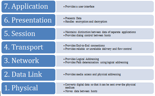
The OSI reference model has seven such layers that can be divided into two groups. The upper layers (Layers 7, 6 and 5) define how applications interact with the host interface, with each other, and the user. The lower four layers (Layers 4, 3, 2 and 1) define how data is transmitted between hosts in a network. Figure 1-7 shows the seven layers and a summary of their functions.
Figure 1-7 Seven Layers of OSI Reference Model
he sections below discuss each layer in detail.
Application Layer
The Application Layer provides the interface between the software application on a system and the network. Remember that this layer does not include the application itself, but provides services that an application requires. One of the easiest ways to understand this layer’s function is to look at how a Web Browser such as Internet Explorer or Firefox works. IE or FF is the application. When it needs to fetch a webpage, it uses the HTTP protocol to send the request and receive the page contents. This protocol resides at the application layer and can be used by an application such as IE or FF to get webpages from web servers across the network. On the other side, the web server application such as Apache or IIS interacts with the HTTP protocol on the Application layer to receive the HTTP request and send the response back.
Presentation Layer
As the name suggest, this layer presents data to the Application layer. The Presentation Layer is responsible for data translation and encoding. It will take the data from the Application layer and translate it into a generic format for transfer across the network. At the receiving end the Presentation layer takes in generically formatted data and translates into the format recognized by the Application layer. An example of this is an EBCDIC to ASCII translation. The OSI model has protocol standards that define how data should be formatted. This layer is also involved in data compression, decompression, encryption, and decryption.
Session Layer
In a host, different applications or even different instances of the same application might request data from across the network. It is the Sessions layer’s responsibility to keep the data from each session separate. It is responsible for setting up, managing and tearing down sessions. It also provides dialog control and coordinates communication between the systems.
Transport Layer
Where the upper layers are related to applications and data within the host, the transport layer is concerned with the actual end-to-end transfer of the data across the network. This layer establishes a logical connection between the two communicating hosts and provides reliable or unreliable data delivery and can provide flow control and error recovery. Although not developed under the OSI Reference Model and not strictly conforming to the OSI definition of the Transport Layer, typical examples of Layer 4 are the Transmission Control Protocol (TCP) and User Datagram Protocol (UDP). These protocols will be discussed in great detail later in this chapter.
Network Layer
To best understand what the Network layer does, consider what happens when you write a letter and use the postal service to send the letter. You put the letter in an envelope and write the destination address as well as your own address so that an undelivered letter can be returned back to you. In network terms, this address is called a logical address and is unique in the network. Each host has a logical address. When the post office receives this letter, it has to ascertain the best path for this letter to reach the destination. Similarly in a network, a router needs to determine the best path to a destination address. This is called path determination. Finally the post office sends the letter out the best path and it moves from post office to post office before finally being delivered to the destination address. Similarly data is moved across network mainly by routers before being finally delivered to the destination.
All these three functions – logical addressing, path determination and forwarding – are done at the Network Layer. Two types of protocols are used for these functions – routed protocols are used for logical addressing and forwarding while routing protocols are used for path determinations. There are many routed protocols and routing protocols available. Some of the common ones are discussed in great detail later the book. Routers function at this layer. Remember that routers only care about the destination network. They do not care about the destination host itself. The task of delivery to the destination host lies on the Data Link Layer.
Data Link Layer
While the Network layer deals with data moving across networks using logical addresses, Data Link layer deals with data moving within a local network using physical addresses. Each host has a logical address and a physical address. The physical address is only locally significant and is not used beyond the network boundaries (across a router). This layer also defines protocols that are used to send and receive data across the media. You will remember from earlier in the chapter that only a single host can send data at a time in a collision domain or else packets will collide and cause a host to back off for sometime. The Data Link layer determines when the media is ready for the host to send the data and also detects collisions and other errors in received data. Switches function at this layer.
Physical Layer
This layer deals with the physical transmission medium itself. It activates, maintains and deactivates the physical link between systems (host and switch for example). This is where the connectors, pin-outs, cables, electrical currents etc. are defined. Essentially this layer puts the data on the physical media as bits and receives it in the same way. Hubs work at this layer.
Data Encapsulation
In the previous sections you learned about various layers of the OSI reference model. Each layer has its distinct function and it interacts with the corresponding layer at the remote end. For example, the transport layer at the source will interact with the transport layer of the destination. For this interaction, each layer adds a header in front of the data from the previous layer. This header contains control information related to the protocol being used at that layer. This process is called encapsulation. This header and the data being sent from one layer to the next lower layer is called a Protocol Data Unit (PDU). Figure 1-8 shows how data gets encapsulated as it travels from layer 7 down to layer 1.
Figure 1-8 Encapsulation in OSI Reference Model
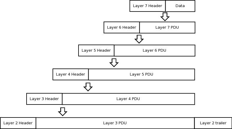
As shown in Figure 1-8, The Application layer adds its protocol dependent header to the data and creates the Layer 7 PDU which is then passed down to the Presentation Layer. This layer then adds its header to the Layer 7 PDU to create the Layer 6 PDU and sends it down to the Session layer. This goes on till Layer 2 receives the Layer 3 PDU. Layer 2 adds a header and a trailer to the Layer 3 PDU to create the Layer 2 PDU that is then sent to Layer 1 for transmission.
At the receiving end, Layer 1 takes the data off the wire and sends it to Layer 2. Here the Layer 2 header and trailer are examined and removed. The resulting Layer 3 PDU is sent to Layer 3. Layer 3 in turn examines the header in the PDU and removes it. The resulting Layer 4 PDU is sent to Layer 4. Similarly, each layer removes the header added by the corresponding layer at the source before sending the data to the upper layer. Finally the Application layer removes the Layer 7 header and sends the data to the application. This process of examining, processing and removing the header is known as decapsulation.
