Ethernet in the term used for a family of standards that define the Network Access layer of the most common type of LAN used today. The various standards differ in terms of speeds supported, cable types and the length of cables. The Institute of Electrical and Electronics Engineers (IEEE) is responsible for defining the various standards since it took over the process in 1980.
To make it easier to understand Ethernet, its functions will be discussed in terms of the OSI reference models’ Data Link and Physical layers. (Remember that Network Access Layer is a combination of these two layers).
IEEE defines various standards at the physical layer while it divides the Data Link functions into the following two sublayers:
- The 802.3 Media Access Control (MAC) sublayer
- The 802.2 Logical Link Control (LLC) sublayer
Even though various physical layer standards are different and require changes at the layer, each of them use the same 802.3 header and the 802.2 LLC sublayer.
The following sections look at the collision detection mechanism used by Ethernet and how Ethernet functions at both the layers.
Collision Detection in Ethernet
Ethernet is a contention media access method that allows all hosts in a network to share the available bandwidth. This means that multiple hosts try to use the media to transfer traffic. If multiple hosts send traffic at the same time, a collision can occur resulting in loss of the frames that collided. Ethernet cannot prevent such collision but it can detect them and take corrective actions to resolve. It uses the Carrier Sense Multiple Access with Collision Detection (CSMA/CD) protocol to do so. This is how CSMA/CD works:
- Hosts looking to transmit a frame listen until Ethernet is not busy.
- When Ethernet is not busy, hosts start sending the frame.
- The source listens to make sure no collision occurred.
- If a collision occurs, the source hosts send a jamming signal to notify all hosts of the collision.
- Each source host randomizes a timer and waits that long before resending the frame that collided.
CSMA/CD works well but it does create some performance issues because:
- Hosts must wait till the Ethernet media is not busy before sending frames. This means only one host can send frames at a time in a collision domain (such as in the case of a network connected to a hub). This also means that a host can either send or receive at one time. This logic is called half-duplex.
- During a collision, no frame makes it across the network. Also, the offending hosts must wait a random time before they can start to resend the frames.
Many networks suffered this sort of performance degradation due to the use of hubs until switches became affordable. In fact, statistics showed that anything over 30 percent utilization caused performance degradation in Ethernet.
Remember that switches break collision domains by providing a dedicated port to each host. This means that hosts connected to a switch only need to wait if the switch is sending frames destined to the host itself.
Half and Full Duplex Ethernet
In the previous section, you learned about the logic called Half Duplex in which a host can only send or receive at one time. In a hub-based network, hosts are connected in a half-duplex mode because they must be able to detect collisions.
When hosts are connected to a switch, they can operate at Full duplex. This means they can send and receive at the same time without worrying about collisions. This is possible because full duplex uses two pairs of wire instead of one pair. Using the two pairs, a point-to-point connection is created between the transmitter of the host to the receiver of the switch and vice versa. So the host sends and receives frames via different pairs of wires and hence need to listed to see if it send frames or not. You should note that CSMA/CD is disabled at both ends when full duplex is used.
Figure 1-17 Full Duplex
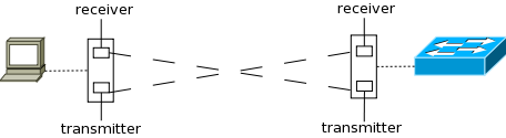
Apart from eliminating collisions, each device actually gets to use twice the bandwidth available because it now has same bandwidth on both pairs of wire and each pair is used separately for sending and receiving.
Figure 1-17 shows how the transmitter on the host’s interface card is connected to the receiver on the switch interface while the receiver on the host interface is connected to the transmitter on the switch interface. Now traffic sent by the host and traffic sent to the host both have a dedicated path with equal bandwidth. If each path has a bandwidth of 100Mbps, the host gets 200Mpbs of dedicated bandwidth to the switch. In case of half-duplex, there would have been only a single path of 100Mbps that would have been used for both receiving and sending traffic.
Ethernet at the Data Link Layer
Ethernet at Data Link layer is responsible for addressing as well as framing the packets received from Network Layer and preparing them for the actual transmission.
Ethernet Addressing
Ethernet Addressing identifies either a single device or a group of devices on a LAN and is called a MAC address. MAC address is 48 bits (6 bytes) long and is written is hexadecimal format. Cisco devices typically write it in a group of four hex digits separated by period while most operating systems write it in groups of two digits separated by a colon. For example, Cisco devices would write a MAC address as 5022.ab5b.63a9 while most operating systems would write it as 50:22:ab:5b:63:a9.
A unicast address identifies a single device. This address is used to identify the source and destination in a frame. Each LAN interface card has a globally unique MAC address. The IEEE defines the format and the assignment of addresses.
Figure 1-18 48bit MAC address
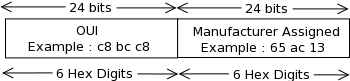
To keep addresses unique, each manufacturer of LAN cards is assigned a code called the organizationally unique identifier (OUI). The first half of every MAC address is the OUI of the manufacturer. The manufacturer assigns the second half of the address while ensuring that the number is not used for any other card. The complete MAC address is then encoded into a ROM chip in the card. Figure 1-18 shows the composition of a MAC address.
MAC address can also identify a group of devices. These are called group addresses. IEEE defines the following two types of group addresses:
- Broadcast Address – This address has a value of FFFF.FFFF.FFFF and means that all devices in the network should process the frame.
- Multicast Address – Multicast addresses are used when a frame needs to go to a group of hosts in the network. When IP multicast packets need to travel over Ethernet a multicast address of 0100.5exx.xxxx is used where xx.xxxx can be any value.
Ethernet Framing
When the Data Link layer receives a packet from the Network layer for transmission, it has to encapsulate the packet in frames. These frames are used to identify the source and destination device by the switch. It also tells the receiving host how to interpret the bits received by the physical layer.
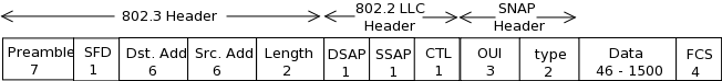
Figure 1-19 IEEE Frame (1997)
![]()
The framing used by Ethernet has changed few times over the year. Xerox defined the original frame. When IEEE took over Ethernet in early 1980s it defined a new frame. In 1997 IEEE finalized the Ethernet frame that took a few components from the Xerox definition and a few from IEEE’s original frame. The finalized frame is shown in Figure 1-19. Table 1-2 lists the fields in the frame, their size and a brief description.
Table 1-2 Frame Fields
| Field | Length in bytes | Description |
| Preamble | 7 | It is used for synchronization. It tells the received device where the header starts. |
| SFD | 1 | Start Frame Delimiter (SFD) tells the receiving device that the next byte is the destination address |
| Destination Address | 6 | Identifies the intended destination of the frame. |
| Source Address | 6 | Identifies the source of the frame. |
| Length | 2 | Contains the length of the data field of the frame. (This field can either be length or type but not both) |
| Type | 2 | Identifies the Network layer protocol whose data is contained in the frame. (This field can either be length or type but not both) |
| Data | 46-1500 | The Network layer data. |
| FCS | 4 | Stores the CRC value which is used to check for errors in transmission. |
The Length/Type field is something you need to understand a little more about. The type field is very important because it tells the receiving end about the protocol whose data is contained in the frame. If the value of the field is less than a hex value of 0600 (decimal value 1536), it signifies that the field is used as a length field in that frame. For cases where this field is used as a length field, either one or two additional headers are added after the Ethernet 802.3 header, but before the layer 3 header. When IP packets are being carried, the Ethernet frame has the following two additional headers:
- An IEEE 802.2 Logical Link Control (LLC) header.
- An IEEE Subnetwork Access Protocol (SNAP) header.
Figure 1-20 shows an Ethernet frame with these two additional headers.
Figure 1-20 802.3 Frame with LLC and SNAP header

Ethernet at the Physical Layer
Ethernet was originally implemented by a group comprised of Digital, Xerox and Intel (DIX). IEEE then took over and created the 802.3 standard. This was a 10Mbps Ethernet that used co-axial cables.
IEEE then extended the 802.3 committee to two new committees known as the 802.3u (FastEthernet) and 802.3ab (Gigabit Ethernet on category 5 cable). Then it created another committee known as the 802.3ae (10Gbps over fiber and co-axial).
On the other hand the Electronics Industries Association and the newer Telecommunication Industries Alliance (EIA/TIA) is the standards body that creates the physical layer specifications for Ethernet. It specifies that a registered jack (RJ) connector with a 4 5 wiring sequence on an unshielded twisted-pair (UTP) cabling should be used with Ethernet. This cable comes in categories where higher category has less of the following two problems associated with them:
- Attenuation – This is the loss of signal strength as it travels the length of the cable. It is measured in decibels.
- Crosstalk – This is the unwanted signal interference from adjacent pairs in the cable.
What this means is that category 5 cable has lesser attenuation and crosstalk than category 3 cables.
Now that you know about the standards bodies involved and what they have done, it is time to look at the various Ethernet standards. Table 1-3 lists the original 3 standards. Remember that each standard is different in terms of Speed, Cable and the Maximum Length of cables.
Table 1-3 Original Ethernet Standards
| Name | Speed | Cable Type | Max Cable length | Connector | Description |
| 10Base2 | 10Mbps | Coaxial | 185 meters | AUI | Known as thinnet, it can support up to 30 hosts in a single segment. A single collision domain across the network. |
| 10Base5 | 10Mbps | Coaxial | 500 meters | AUI | Known as thicknet, it can support up to 100 users in a single segment. A single collision domain across the network. |
| 10BaseT | 10Mbps | UTP | 100 meters | RJ45 | The first standard to use UTP cable with RJ45. A single host can be connected to a segment or wire. It required use of hubs to connect multiple hosts. |
Table 1-4 shows the extended Ethernet Standards.
Table 1-4 Extended Ethernet Standards
| Name | Speed | Cable Type | Maximum Cable Length | Connector |
| 100BaseTX (IEEE 802.3u) | 100 Mbps | UTP cat. 5, 6 or 7 two-pair wiring | 100 meters | RJ45 |
| 100BaseFX (IEEE 802.3u) | 100Mbps | Multimode Fiber | 412 meters | ST or SC connector |
| 1000BaseCX (IEEE 802.3z) | 1000Mpbs | Copper twisted pair called twinax | 25 meters | DE-9 or 8P8C |
| 1000BaseSX(IEEE 802.3z) | 1000Mbps | Multimode Fiber | 220 meters | ST or SC connector |
| 1000BaseLX(IEEE 802.3z) | 1000Mpbs | Single mode Fiber | 5km | ST or SC connector |
| 1000BaseT(IEEE 802.3ab) | 1000Mpbs | Cat 5 UTP | 100 meters | RJ45 |
Ethernet Cabling
When connecting different kinds of devices to each other, different kinds of cabling is used. The following three types of Ethernet cablings exist:
- Straight-through cable (a normal patch cable)
- Crossover cable
- Rolled cable
The three cabling types are discussed below:
Straight-Though – A UTP cable has 8 wires. A straight-through uses 4 out of these 8 wires. Figure 1-21 shows the configuration of the wire on both ends in a straight-through cable. Notice that only wires 1, 2, 3 and 6 are used and they connect straight to corresponding number on the other end.
Figure 1-21 Wire configuration in Straight-Through cable

Crossover – Crossover cable also uses the same four wires that are used in straight-through cable but different pins are connected here. Figure 1-22 shows the configuration of the wires in a crossover cable.
Figure 1-22 Wire configuration in Crossover cable

Crossover cable is used to connect:
- Host to Host
- Switch to Switch
- Hub to Hub
- Switch to Hub
- Router to a host
Any easy way to remember this is that similar devices are connected to each other using crossover cables.
Rolled Cable – A rolled cable cannot be used for any Ethernet connection. It is used for connecting to a router’s or a switch’s console port from your host’s serial communication (com) port. Every Cisco router and switch has a console port that is used for initial configuration. All 8 wires are used in this cable and each wire connects to the opposite number on the end (1 to 8, 2 to 7, 3 to 6 etc). Figure 1-23 shows the wire configuration.
Figure 1-23 Wire configuration in Crossover cable

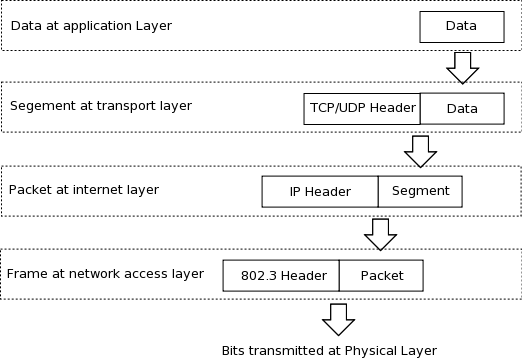
Data Encapsulation in TCP/IP Model
The last thing you need to know about TCP/IP model is the Data encapsulation process and PDUs. As in case of the OSI reference model, the data is encapsulated in a header (and trailer in case of Network layer) to create a Protocol Data Unit (PDU) and is passed down to the next layer. Though you are aware of the process, you must know the names of each layer’s PDU. The PDU in TCP/IP model are:
- Transport Layer -> Segment
- Internet Layer -> Packet
- Network Access Layer -> Frame
Figure 1-24 shows the encapsulation process in TCP/IP model.
Figure 1-24 Data encapsulation in TCP/IP Model