We will discuss two point-to-point WAN protocols available on serial interfaces of Cisco routers namely High-Level Data Link Control (HDLC) and Point-to-Point Protocol. The two protocols are inter-related though PPP is significantly more feature-rich and advanced than HDLC.
Table 12-1 Encapsulation Chart
| Encapsulation | Leased Line | Circuit Switched | Packet Switched |
| HDLC | Yes | Yes | No |
| PPP | Yes | Yes | No |
| Frame Relay | No | No | Yes |
We will explain how to configure leased lines between two routers, using both HDLC and PPP.
HDLC Concepts
High-Level Data Link Protocol (HDLC) is a simple data link protocol that performs a few basic functions on point-to-point serial links. The standard HDLC frame does not have a protocol type field to identify the type of packet carried inside the HDLC frame. The HDLC trailer has a Frame Check Sequence (FCS) field that allows the receiving router to decide if the frame had errors in transit and discard the frame if needed.

The absence of a protocol type field in the HDLC header posed a problem for links that carried traffic from more than one Layer 3 protocol. Cisco, therefore, added an extra Type field to the HDLC header, creating a Cisco-specific version of HDLC. The frame format of this Cisco version of HDLC is shown in Figure 12-4 and it is this HDLC frame found on all HDLC serial links connecting Cisco routers. Cisco routers can support multiple network layer protocols on the same HDLC link. For example an HDLC link between two Cisco routers can forward both IPv4 and IPv6 packets because the Type field can identify which type of packet is carried inside each HDLC frame.
Figure 12-3 HDLC Framing
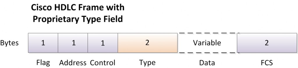
The Address and Control fields do not have much work to do these days. For example, only two routers are connected to each other on a point-to-point serial link. When a router sends a frame it is obvious that the frame is destined for the only other router on the link. You may be wondering why HDLC has an Address field at all. In years past, telcos offered multidrop circuits which included more than two devices with more than one possible destination, requireing an Address field to identify the correct destination. Both Address and Control fields had important roles in those days, but today they are not important.
HDLC Configuration
Cisco IOS Software uses HDLC as the data link protocol, by default, on serial interfaces. In order to establish a functional point-to-point leased line connection between two routers, you first need to order a leased line. Once the leased line is provisioned, you need to complete the required cabling between routers at the two ends and CSU/DSUs. In addition to that, you just need to configure IP addresses and probably a no shutdown command if the interface is administratively shutdown. The point-to-point WAN connection would become functional with HDLC as the Layer 2 protocol.
However, many optional commands exist for serial links and we will configure a point-to-point serial links between two routers as shown in Figure 12-3, exploring some of those commands.
Figure 12-4 HDLC Configuration
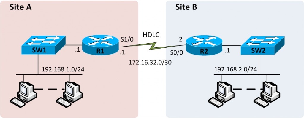
First of all, let’s configure the interface IP address on R1 using the ip address command in interface configuration mode.
If an encapsulation command already exists on the interface, for a non-HDLC protocol, we will have to enable HDLC using the encapsulation hdlc command in interface configuration mode. Alternatively, you can make the interface revert back to its default encapsulation by using either no encapsulation or default encapsulation command to disable the currently enabled protocol.
If the line status of the interface is administratively down, you must enable the interface using the no shutdown command. That sort of concludes our configuration. However, there are some optional commands that do not have any impact on whether our HDLC link works or not. It is always a good practice to configure a description of the purpose of the interface using the description command in interface configuration mode. You can also configure the speed of the link using the bandwidth command that takes its parameters in kbps. The bandwidth command does not set the actual bandwidth of the link which is rather determined by clocking provided by the CSU/DSU. However it is good practice to set the bandwidth equal to the actual speed of the link. Let’s now go ahead and actually configure R1.
R1>enable
R1#configure terminal
Enter configuration commands, one per line. End with CNTL/Z.
R1(config)#interface Serial1/0
R1(config-if)#ip address 172.16.32.1 255.255.255.252
R1(config-if)#encapsulation hdlc
R1(config-if)#bandwidth 64
R1(config-if)#description Serial link to R2 with HDLC encapsulation
R1(config-if)#no shutdown
R1(config-if)#end
R1#
R2 will have a similar configuration.
R2>enable
R2#configure terminal
Enter configuration commands, one per line. End with CNTL/Z.
R2(config)#interface Serial0/0
R2(config-if)#ip address 172.16.32.2 255.255.255.252
R2(config-if)#encapsulation hdlc
R2(config-if)#bandwidth 64
R2(config-if)#description Serial link to R1 with HDLC encapsulation
R2(config-if)#no shutdown
R2(config-if)#end
R2#
Let’s now verify if the link is operational.
Serial1/0 is up, line protocol is up
Hardware is M4T
Description: Serial link to R2 with HDLC encapsulation
Internet address is 172.16.32.1/30
MTU 1500 bytes, BW 64 Kbit, DLY 20000 usec,
reliability 255/255, txload 3/255, rxload 3/255
Encapsulation HDLC, crc 16, loopback not set
Keepalive set (10 sec)
Restart-Delay is 0 secs
Last input 00:00:04, output 00:00:04, output hang never
Last clearing of “show interface” counters never
<Some output omitted for brevity>
In addition, you can also use show ip interface brief and show interface description commands to verify interface status and configuration.
R1#show ip int brief
Interface IP-Address OK? Method Status Protocol
FastEthernet0/0 192.168.1.1 YES NVRAM up up
Serial1/0 172.16.32.1 YES manual up up
Serial1/1 unassigned YES NVRAM administratively down down
Serial1/2 unassigned YES NVRAM administratively down down
Serial1/3 unassigned YES NVRAM administratively down down
R1#show interfaces description
Interface Status Protocol Description
Fa0/0 up up
Se1/0 up up Serial link to R2 with HDLC encapsulation
Se1/1 admin down down
Se1/2 admin down down
Se1/3 admin down down
The router will use a serial interface only when it is in the up/up state, as shown in the highilighted line of the output of show commands above. The first up refers to the Layer 1 status while the second up indicates Layer 2 status.
In a production environment, the two routers would be connected to CSU/DSUs to form a poin-to-point serial link. However, in a lab environment you may need to connect two routers back-to-back without a real leased line or CSU/DSUs. There are two ways to get this done. One method is to use a device known as modem eliminator, which as the name says eliminated the need to have CSU/DSUs and appears to be a modem for both routers. Another method is to connect the two routers directly using back-to-back cables. In this case you have to configure clocking on one of the two routers using the clock rate command in interface configuration mode. This command should be used only on the one router with the DCE cable connected to it. If you are not sure which router has the DCE cable connected to it, you may use the show controllers command to find out.