VLANs provide traffic separation at layer 2 of the OSI model. Hosts in a VLAN can communicate freely and directly with other hosts on the same VLAN and it includes unicasts, multicasts, and broadcasts. All three types of frames can flow freely and directly between any two hosts that are on the same VLAN regardless of their physical location on a switched network. But what if hosts on two different VLANs need to communicate? In such situation you need a layer 3 device, either a router or a layer 3 switch. Such communication is simply not possible within the bounds of a layer 2 only network.
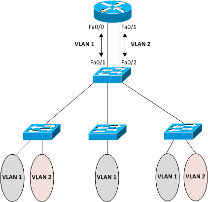
Have a look at Figure 7-7, where our switched network has two VLANs: VLAN 1 and VLAN 2. Hosts in VLAN 1 need to communicate with hosts in VLAN 2. We know that this kind of communication is not possible in our layer 2 only switched network and we need a layer 3 device. One possible solution to achieve communication between the two VLANs can be to introduce a router into the picture such that the router has two LAN interfaces Fa0/0 and Fa0/1 one for each VLAN. These two interfaces are connected to two access switch ports Fa0/1 and Fa0/2 in VLANs 1 and 2 respectively. The router interfaces connected to these switch ports each have an IP address configured in the subnet corresponding to the associated VLAN. From the standpoint of the router, the two VLANs are merely two different subnets connected to two different router interfaces and the router essentially performs routing to move traffic between the two VLANs. Please remember that best practices dictate using a separate IP subnet for each VLAN. As you can see, this scheme requires one dedicated interface on the router for each VLAN in your switched network. You can imagine the solution does not scale well when you have several VLANs in your switched network.
Figure 7-8 Router with Separate Interface for Each VLAN
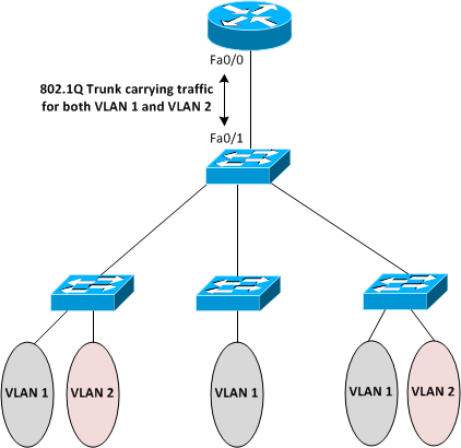
Now, have a look at Figure 7-8 below, which is an alternate and more efficient way of achieving routing between different VLANs using a router. Here we have only one router interface Fa0/0 connected to the switch port Fa0/1. The link is configured as an 802.1Q carrying traffic for both VLAN 1 and VLAN 2. There is one sub-interface per VLAN configured on the router with IP addresses configured on subinterfaces rather than the physical interface. This is the key difference that we have only one physical connection from the router to the switch regardless of the number of VLANs. This solution, also called router-on-a-stick, is more efficient and scalable to a large number of VLANs. Most switches today are not just layer 2 devices but are multilayer switches and inter-VLAN routing can be achieved using switches alone without involving a router at all. You will see this concept on the CCNA exam and you must remember that the link from the switch to the router must be a trunked link and the router’s interface must be at least a Fast Ethernet interface. These two things very important and will be on the exam!
Figure 7-9 Router on a Stick