You should have a good understanding of Frame Relay by now and its time to get your hands dirty with some configuration. Frame Relay configuration has any options, yet the actual configuration you perform can be very basic depending on how many default settings can be used. Cisco IOS Software uses the following defaults for Frame Relay:
- LMI Cisco IOS automatically senses the LMI type by default and this feature is referred to as LMI autosense. If you manually configure the LMI using the frame-relay lmi-type command, LMI autosense is silently disabled.
- IARP Cisco IOS automatically discovers the next-hop IP address associated with a DLCI or VC using Inverse Address Resolution Protocol (IARP). You can also create a mapping between a DLCI and next-hop IP address manually using frame-relay map ip command.
- Encapsulation Cisco IOS uses Cisco encapsulation for Frame Relay and if you are using only Cisco routers, this default setting works fine without any additional configuration.
You are familiar with the concept of physical and logical sub-interfaces. For example, you may configure several sub-interfaces on a single Fast Ethernet physical interface on a Cisco router. Frame Relay is a Layer 2 WAN protocol that cand be configured on physical serial links. In addition to physical interfaces, you can also configure two types of logical interfaces for Frame Relay – point-to-point and multipoint. We will introduce you to some of the specifics of Frame Relay configuration for these different interface types.
In certain cases, you may have a working Frame Relay connection by just using a single command encpsulation frame-relay, and leaving everything else to default values. However, you should be familiar with the many configuration options and when they are used. Frame Relay is the source of many tricky questions on CCNA, CCNP, and beyond.
Here is your step-by-step guide to configuring Frame Relay:
- The first step should always be to configure the physical interface to use Frame Relay encapsulation using the command encapsulation frame-relay in interface configuration mode.
- Configure an IP address on the interfaces or sub-interface using the good old ip address command.
- Optionally, configure the LMI type of each physical interace using the frame-relay lmi-type command.
- Optionally, change the default Frame Relay encapsulation using the command encapsulation frame-relay. If you use the command on the interface (or sub-interface), it will change the encapsulation for all VCs on the interface (or sub-interface. If you want to change the encapsulation only for a specific VC, you should use the ietf keyword with the command frame-relay interface-dlci (point-to-point sub-interfaces) or frame-relay map.
- The default is to use the Inverse ARP (IARP) to map the DLCI to the IP address of next-hop router. However, you can also configure static mapping using the frame-relay map ip ip-address dlci broadcast command.
- There are two ways to associate one DLCI to point-to-point or multiple DLCIs to multipoint interfaces. The first involves using the frame-relay interface-dlci dlci sub-interface command. The second involves using the frame-relay map ip ip-address dlci broadcast sub-interface command.
We are going to present three different Frame Relay configuration examples to see all those configuration steps in action. The examples correspond to the three Frame Relay scenarios we presented earlier in the chapter. We will also introduce you to several show commands that are useful to verify your configuration and troubleshoot if something is not working as expected.
Configuration – Single Subnet for all Routers
The first option involves a single IP subnet for all routers/DTEs, with IP addresses configured on physical serial interfaces, as shown in Figure 12-17.
Figure 12-17 Configuration – Single Subnet for all Routers
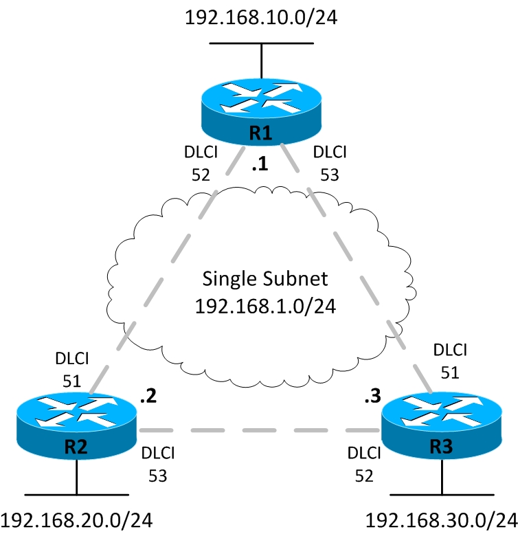
We will use a single class C private subnet 192.168.1.0/24 in this example. Table 12-5 should serve as a reference for all configuration in this section.
Table 12-5 Configuration Table
| Router | Interface / Type | DLCI | IP Address |
| R1 | Serial 0/0 / physical | Learned via InARP | 192.168.1.1/24 |
| R2 | Serial 0/0 / physical | Learned via InARP | 192.168.1.2/24 |
| R3 | Serial 0/0 / physical | Learned via InARP | 192.168.1.3/24 |
We are going to configure IP addresses on physical serial interfaces of all three routers. Also, we will not configure or map any DLCIs manually. We will rather rely on Inverse ARP, enabled by default on serial interfaces with Frame Relay encapsulation, for learning DLCIs. The router connected to the Frame Relay network learns DLCI information from the LMI status messages sent by the Frame Relay switch to the router.
The ultimate goal of a Frame Relay network is to enable hosts on a LAN communicate with hosts on remote LANs. We will use EIGRP to propagate routing information to achieve that goal. The configuration is pretty simple here and we are just enabling Frame Relay encapsulation using the encapsulation frame-relay command.
R1# configure terminal
R1(config)# interface Serial0/0
R1(config-if)# ip address 192.168.1.1 255.255.255.0
R1(config-if)# encapsulation frame-relay
R1(config-if)# no shutdown
R1(config-if)# exit
R1(config-if)# interface FastEthernet1/0
R1(config-if)# ip address 192.168.10.1 255.255.255.0
R1(config-if)# no shutdown
R1(config-if)# exit
R1(config)# router eigrp 100
R1(config-router)# network 192.168.1.0
R1(config-router)# network 192.168.10.0
R1(config-router)# end
R1#
The configuration for R2 is very similar.
R2# configure terminal
R2(config)# interface Serial0/0
R2(config-if)# ip address 192.168.1.2 255.255.255.0
R2(config-if)# encapsulation frame-relay
R2(config-if)# no shutdown
R2(config-if)# exit
R2(config-if)# interface FastEthernet1/0
R2(config-if)# ip address 192.168.20.1 255.255.255.0
R2(config-if)# no shutdown
R2(config-if)# exit
R2(config)# router eigrp 100
R2(config-router)# network 192.168.1.0
R2(config-router)# network 192.168.20.0
R2(config-router)# end
R2#
There are no surprises with the configuration of R3 either.
R3# configure terminal
R3(config)# interface Serial0/0
R3(config-if)# ip address 192.168.1.3 255.255.255.0
R3(config-if)# encapsulation frame-relay
R3(config-if)# no shutdown
R3(config-if)# exit
R3(config-if)# interface FastEthernet1/0
R3(config-if)# ip address 192.168.30.1 255.255.255.0
R3(config-if)# no shutdown
R3(config-if)# exit
R3(config)# router eigrp 100
R3(config-router)# network 192.168.1.0
R3(config-router)# network 192.168.30.0
R3(config-router)# end
R3#
We are done with our Frame Relay configuration here, and it’s time to verify if it works as expected. A good starting point for Frame Relay verification can be the show frame-relay map command.
Serial0/0 (up): ip 192.168.1.2 dlci 52(0x34,0xC40), dynamic,
broadcast,, status defined, active
Serial0/0 (up): ip 192.168.1.3 dlci 53(0x35,0xC50), dynamic,
broadcast,, status defined, active
The above output is full of useful information. First, it tells you that two DLCIs are available on the interface Serial0/0 that correspond to two VCs. IP addresses 192.168.1.2 and 192.168.1.3 are dynamically mapped to DLCIs 52 and 53 respectively. The DLCIs are both learned from the Frame Relay switch through LMI Status messages sent from the switch to the router, and both are active which is the desired state.
Here is the output of show frame-relay lmi command executed on R1.
R1#show frame-relay lmi
LMI Statistics for interface Serial0/0 (Frame Relay DTE) LMI TYPE = CISCO
Invalid Unnumbered info 0 Invalid Prot Disc 0
Invalid dummy Call Ref 0 Invalid Msg Type 0
Invalid Status Message 0 Invalid Lock Shift 0
Invalid Information ID 0 Invalid Report IE Len 0
Invalid Report Request 0 Invalid Keep IE Len 0
Num Status Enq. Sent 9 Num Status msgs Rcvd 9
Num Update Status Rcvd 0 Num Status Timeouts 0
Last Full Status Req 00:00:24 Last Full Status Rcvd 00:00:24
The above output provides detailed LMI statistics for Frame Relay interfaces on the router, in this case only Serial0/0. The first thing to notice is that the LMI type is cisco which is expected as we did not explicitly configured it and the router defaulted to cisco. The number of status enquiry messages sent equals the number of status messages received from the Frame Relay switch. These numbers increment by one almost every 10 seconds under normal conditions. The last output line is interesting as it shows the time elapsed since the last full status was received. You may recall that regular status messages are received in response to status enquiry messages every 10 seconds. However there is a full status message sent by the Frame Relay switch every 60 seconds that include complete information about all DLCIs.
We will run a quick debug on R1 to see what LMI messages are being exchanged. We include a sample output of debug frame-relay lmi command for R1 here. You can see a StEnq (status enquiry) message sent out the interface Serial0/0 by the Frame Relay DTE/router. A Status message from Frame Relay DCE/switch arrives at interface Serial0/0 shortly after that.
Frame Relay LMI debugging is on
Displaying all Frame Relay LMI data
R1#
*Mar 1 00:00:40.295: Serial0/0(out): StEnq, myseq 3, yourseen 2, DTE up
*Mar 1 00:00:40.299: datagramstart = 0x7A00714, datagramsize = 13
*Mar 1 00:00:40.299: FR encap = 0xFCF10309
*Mar 1 00:00:40.303: 00 75 01 01 01 03 02 03 02
*Mar 1 00:00:40.307:
*Mar 1 00:00:40.327: Serial0/0(in): Status, myseq 3, pak size 13
*Mar 1 00:00:40.327: RT IE 1, length 1, type 1
*Mar 1 00:00:40.331: KA IE 3, length 2, yourseq 3 , myseq 3
The show frame-relay pvc command can be used to view PVC status and some traffic statistics.
R1#show frame-relay pvc
PVC Statistics for interface Serial0/0 (Frame Relay DTE)
Active Inactive Deleted Static
Local 2 0 0 0
Switched 0 0 0 0
Unused 0 0 0 0
DLCI = 52, DLCI USAGE = LOCAL, PVC STATUS = ACTIVE, INTERFACE = Serial0/0
input pkts 17 output pkts 16 in bytes 1022
out bytes 986 dropped pkts 0 in pkts dropped 0
out pkts dropped 0 out bytes dropped 0
in FECN pkts 0 in BECN pkts 0 out FECN pkts 0
out BECN pkts 0 in DE pkts 0 out DE pkts 0
out bcast pkts 10 out bcast bytes 610
5 minute input rate 0 bits/sec, 0 packets/sec
5 minute output rate 0 bits/sec, 0 packets/sec
pvc create time 00:07:28, last time pvc status changed 00:07:28
DLCI = 53, DLCI USAGE = LOCAL, PVC STATUS = ACTIVE, INTERFACE = Serial0/0
input pkts 15 output pkts 16 in bytes 914
out bytes 958 dropped pkts 0 in pkts dropped 0
out pkts dropped 0 out bytes dropped 0
in FECN pkts 0 in BECN pkts 0 out FECN pkts 0
out BECN pkts 0 in DE pkts 0 out DE pkts 0
out bcast pkts 10 out bcast bytes 610
5 minute input rate 0 bits/sec, 0 packets/sec
5 minute output rate 0 bits/sec, 0 packets/sec
pvc create time 00:07:30, last time pvc status changed 00:07:30
We may examine the routing table of R1, which shows some EIGRP learned routes. It indicates that the PVCs are active and some routing information has been exchanged over those PVCs by EIGRP.
R1#show ip route
<Some output omitted for brevity.>
Gateway of last resort is not set
D 192.168.30.0/24 [90/2172416] via 192.168.1.3, 00:06:46, Serial0/0
C 192.168.10.0/24 is directly connected, FastEthernet1/0
D 192.168.20.0/24 [90/2172416] via 192.168.1.2, 00:07:39, Serial0/0
C 192.168.1.0/24 is directly connected, Serial0/0
The ultimate test is to verify end-to-end connectivity across all three VCs we have, which can be done by going to each of the three routers one by one and pinging the other two routers.
R1#ping 192.168.1.2
Type escape sequence to abort.
Sending 5, 100-byte ICMP Echos to 192.168.1.2, timeout is 2 seconds:
!!!!!
Success rate is 100 percent (5/5), round-trip min/avg/max = 16/40/56 ms
We should also verify connectivity between the local-area networks (LANs) attached to routers.
Type escape sequence to abort.
Sending 5, 100-byte ICMP Echos to 192.168.20.1, timeout is 2 seconds:
Packet sent with a source address of 192.168.10.1
!!!!!
Success rate is 100 percent (5/5), round-trip min/avg/max = 36/40/44 ms
We are not including all the ping tests here for the sake of brevity, but we have achieved end-to-end reachability at this point.
Configuration – One Subnet per VC
The second configuration example involves one subnet per virtual circuit, as shown in Figure 12-16. It is a special case of partial mesh topology also known as hub-and-spoke. We will also introduce you to some additional Frame Relay configuration options not seen in the first example above.
Figure 12-18 Configuration – One Subnet per VC
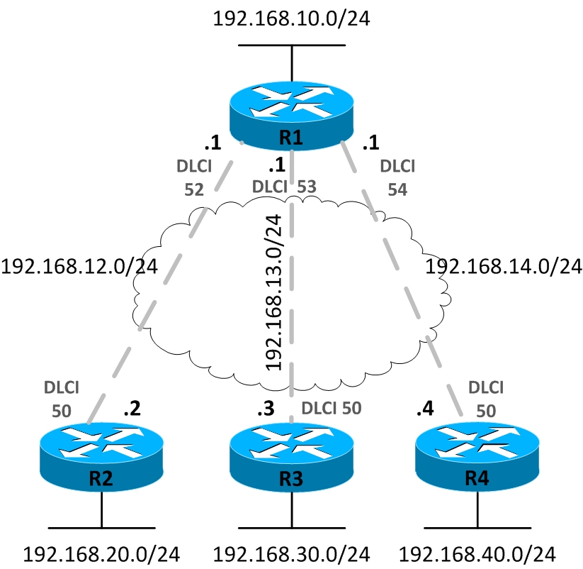
We will use sub-interfaces in this example and manually assign DLCIs to sub-interfaces, per the following table.
Table 12-6 Configuration Table
| Router | Interface / Type | DLCI | IP Address |
| R1 | Serial 0/0.2 / point-to-point | 52 | 192.168.12.1/24 |
| R1 | Serial 0/0.3 / point-to-point | 53 | 192.168.13.1/24 |
| R1 | Serial 0/0.4 / point-to-point | 54 | 192.168.14.1/24 |
| R2 | Serial 0/0.1 / point-to-point | 51 | 192.168.12.2/24 |
| R3 | Serial 0/0.1 / point-to-point | 51 | 192.168.13.3/24 |
| R4 | Serial 0/0.1 / point-to-point | 51 | 192.168.14.4/24 |
We are going to use point-to-point sub-interfaces, and DLCIs assigned manually to sub-interfaces. Even though the router can learn DLCIs through LMI messages, but those DLCI’s will all be assigned to the physical interface by default, rather than point-to-point sub-interface. However Inverse ARP is still used to map remote IP adddresses to DLCIs.
R1#configure terminal
Enter configuration commands, one per line. End with CNTL/Z.
R1(config)#interface Serial0/0
R1(config-if)#encapsulation frame-relay
R1(config-if)#no shutdown
R1(config-if)#interface Serial0/0.2 point-to-point
R1(config-subif)#ip address 192.168.12.1 255.255.255.0
R1(config-subif)#frame-relay interface-dlci 52
R1(config-fr-dlci)#interface Serial0/0.3 point-to-point
R1(config-subif)#ip address 192.168.13.1 255.255.255.0
R1(config-subif)#frame-relay interface-dlci 53
R1(config-fr-dlci)#interface Serial0/0.4 point-to-point
R1(config-subif)#ip address 192.168.14.1 255.255.255.0
R1(config-subif)#frame-relay interface-dlci 54
R1(config-fr-dlci)#interface FastEthernet1/0
R1(config-if)#ip address 192.168.10.1 255.255.255.0
R1(config-if)#no shutdown
R1(config-if)#exit
R1(config)#router eigrp 100
R1(config-router)#network 192.168.12.0
R1(config-router)#network 192.168.13.0
R1(config-router)#network 192.168.14.0
R1(config-router)#network 192.168.10.0
R1(config-router)#end
R1#
R2 has a similar configuration.
R2#configure terminal
Enter configuration commands, one per line. End with CNTL/Z.
R2(config)#
R2(config)#interface Serial0/0
R2(config-if)#encapsulation frame-relay
R2(config-if)#no shutdown
R2(config-if)#interface Serial0/0.1 point-to-point
R2(config-subif)#ip address 192.168.12.2 255.255.255.0
R2(config-subif)#frame-relay interface-dlci 51
R2(config-fr-dlci)#interface FastEthernet1/0
R2(config-if)#ip address 192.168.20.1 255.255.255.0
R2(config-if)#no shutdown
R2(config-if)#router eigrp 100
R2(config-router)#network 192.168.12.0
R2(config-router)#network 192.168.20.0
|R2(config-router)#end
R2#
R3 has pretty much similar configuration as well.
R3#configure terminal
Enter configuration commands, one per line. End with CNTL/Z.
R3(config)#interface Serial0/0
R3(config-if)#encapsulation frame-relay
R3(config-if)#no shutdown
R3(config-if)#interface Serial0/0.1 point-to-point
R3(config-subif)#ip address 192.168.13.3 255.255.255.0
R3(config-subif)#frame-relay interface-dlci 51
R3(config-fr-dlci)#interface FastEthernet1/0
R3(config-if)#ip address 192.168.30.1 255.255.255.0
R3(config-if)#no shutdown
R3(config-if)#router eigrp 100
R3(config-router)#network 192.168.13.0
R3(config-router)#network 192.168.30.0
R3(config-router)#end
R3#
R4 too has a single PVC to R1 like R2 and R3. R1 happens to be the hub in this hub-and spoke topology. This topology is commonly used in real-world Frame Relay networks where a large number of remote offices are connected to the company headquarters.
R4#configure terminal
Enter configuration commands, one per line. End with CNTL/Z.
R4(config)#interface Serial0/0
R4(config-if)#encapsulation frame-relay
R4(config-if)#no shutdown
R4(config-if)#interface Serial0/0.1 point-to-point
R4(config-subif)#ip address 192.168.14.4 255.255.255.0
R4(config-subif)#frame-relay interface-dlci 51
R4(config-fr-dlci)#interface FastEthernet1/0
R4(config-if)#ip address 192.168.40.1 255.255.255.0
R4(config-if)#no shutdown
R4(config-if)#router eigrp 100
R4(config-router)#network 192.168.14.0
R4(config-router)#network 192.168.40.0
R4(config-router)#end
R4#
Let’s verify that PVCs are established between R1 and the rest of routers by using the show frame-relay map command.
Serial0/0.3 (up): point-to-point dlci, dlci 53(0x35,0xC50), broadcast
status defined, active
Serial0/0.2 (up): point-to-point dlci, dlci 52(0x34,0xC40), broadcast
status defined, active
Serial0/0.4 (up): point-to-point dlci, dlci 54(0x36,0xC60), broadcast
status defined, active
Let’s examine the status of Frame Relay sub-interfaces on R1.
Interface IP-Address OK? Method Status Protocol
Serial0/0 unassigned YES NVRAM up up
Serial0/0.2 192.168.12.1 YES NVRAM up up
Serial0/0.3 192.168.13.1 YES NVRAM up up
Serial0/0.4 192.168.14.1 YES NVRAM up up
Serial0/1 unassigned YES NVRAM administratively down down
Serial0/2 unassigned YES NVRAM administratively down down
Serial0/3 unassigned YES NVRAM administratively down down
FastEthernet1/0 192.168.10.1 YES NVRAM up up
The PVCs are active and we have end-to-end connectivity at this point.
Configuration – A Mix of Full and Partial Mesh
The third and last configuration example involves a mix of full and partial mesh, as shown in Figure 12-17. We are going to have both point-to-point and multipoint sub-interfaces. Multipoint interfaces are logical Frame Relay sub-interfaces but they can terminate more than one PVCs just like physical serial interfaces.
Figure 12-19 Configuration – A Mix of Full and Partial Mesh
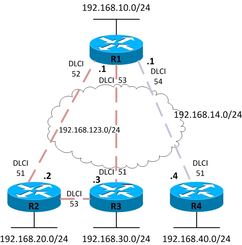
Table 12-7 Configuration Table
| Router | Interface / Type | DLCI | IP Address |
| R1 | Serial 0/0.123 / multipoint | 52, 53 | 192.168.123.1/24 |
| R1 | Serial 0/0.4 / point-to-point | 54 | 192.168.14.1/24 |
| R2 | Serial 0/0.123 / multipoint | 51, 53 | 192.168.123.2/24 |
| R3 | Serial 0/0.123 / multipoint | 51, 53 | 192.168.123.3/24 |
| R4 | Serial 0/0.1 / point-to-point | 51 | 192.168.14.4/24 |
R1 has a multipoint Frame Relay sub-interface connected to subnet 192.168.123.0/24 while a point-to-point subinterface terminates the PVC to R4.
R1#configure terminal
Enter configuration commands, one per line. End with CNTL/Z.
R1(config)#interface Serial0/0
R1(config-if)#encapsulation frame-relay
R1(config-if)#no shutdown
R1(config-if)#interface Serial0/0.4 point-to-point
R1(config-subif)#ip address 192.168.14.1 255.255.255.0
R1(config-subif)#frame-relay interface-dlci 54
R1(config-fr-dlci)#interface Serial0/0.123 multipoint
R1(config-subif)#ip address 192.168.123.1 255.255.255.0
R1(config-subif)#frame-relay interface-dlci 52
R1(config-fr-dlci)#frame-relay interface-dlci 53
R1(config-fr-dlci)#interface FastEthernet1/0
R1(config-if)#ip address 192.168.10.1 255.255.255.0
R1(config-if)#no shutdown
R1(config-if)#router eigrp 100
R1(config-router)#network 192.168.14.0
R1(config-router)#network 192.168.123.0
R1(config-router)#network 192.168.10.0
R1(config-router)#end
R1#
R1 has a multipoint Frame Relay sub-intefaces connected to the subnet 192.168.123.0/24 as well.
R2#configure terminal
Enter configuration commands, one per line. End with CNTL/Z.
R2(config)#interface Serial0/0
R2(config-if)#encapsulation frame-relay
R2(config-if)#no shutdown
R2(config-if)#interface Serial0/0.123 multipoint
R2(config-subif)#ip address 192.168.123.2 255.255.255.0
R2(config-subif)#frame-relay interface-dlci 51
R2(config-fr-dlci)#frame-relay interface-dlci 53
R2(config-fr-dlci)#interface FastEthernet1/0
R2(config-if)#ip address 192.168.20.1 255.255.255.0
R2(config-if)#no shutdown
R2(config-if)#router eigrp 100
R2(config-router)#network 192.168.123.0
R2(config-router)#network
R2(config-router)#end
R2#
R3 also shares the subnet 192.168.123.0/24 via its Frame Relay multipoint sub-interface that terminates two PVCs.
R3#configure terminal
Enter configuration commands, one per line. End with CNTL/Z.
R3(config)#interface Serial0/0
R3(config-if)#encapsulation frame-relay
R3(config-if)#no shutdown
R3(config-if)#interface Serial0/0.123 multipoint
R3(config-subif)#ip address 192.168.123.3 255.255.255.0
R3(config-subif)#frame-relay interface-dlci 51
R3(config-fr-dlci)#frame-relay interface-dlci 52
R3(config-fr-dlci)#interface FastEthernet1/0
R3(config-if)#ip address 192.168.30.1 255.255.255.0
R3(config-if)#no shutdown
R3(config-if)#router eigrp 100
R3(config-router)#network 192.168.123.0
R3(config-router)#network 192.168.30.0
R3(config-router)#end
R3#
R4 has a point-to-point sub-interface only terminating a PVC to R1.
R4#configure terminal
Enter configuration commands, one per line. End with CNTL/Z.
R4(config)#interface Serial0/0
R4(config-if)#encapsulation frame-relay
R4(config-if)#no shutdown
R4(config-if)#interface Serial0/0.1 point-to-point
R4(config-subif)#ip address 192.168.14.4 255.255.255.0
R4(config-subif)#frame-relay interface-dlci 51
R4(config-fr-dlci)#interface FastEthernet1/0
R4(config-if)#ip address 192.168.40.1 255.255.255.0
R4(config-if)#no shutdown
R4(config-if)#router eigrp 100
R4(config-router)#network 192.168.14.0
R4(config-router)#network 192.168.40.0
R4(config-router)#end
R4#
It’s time to view the Frame Relay DLCI to IP address mappings learned via InARP, using show frame-relay map command on R1.
Serial0/0.123 (up): ip 192.168.123.2 dlci 52(0x34,0xC40), dynamic,
broadcast,, status defined, active
Serial0/0.123 (up): ip 192.168.123.3 dlci 53(0x35,0xC50), dynamic,
broadcast,, status defined, active
Serial0/0.4 (up): point-to-point dlci, dlci 54(0x36,0xC60), broadcast
status defined, active
We will use the show frame-relay pvc command on R4, to examine the status of PVC.
R4#show frame-relay pvc
PVC Statistics for interface Serial0/0 (Frame Relay DTE)
Active Inactive Deleted Static
Local 1 0 0 0
Switched 0 0 0 0
Unused 0 0 0 0
DLCI = 51, DLCI USAGE = LOCAL, PVC STATUS = ACTIVE, INTERFACE = Serial0/0.1
input pkts 17 output pkts 23 in bytes 1192
out bytes 2970 dropped pkts 0 in pkts dropped 0
out pkts dropped 0 out bytes dropped 0
in FECN pkts 0 in BECN pkts 0 out FECN pkts 0
out BECN pkts 0 in DE pkts 0 out DE pkts 0
out bcast pkts 17 out bcast bytes 2630
5 minute input rate 0 bits/sec, 0 packets/sec
5 minute output rate 0 bits/sec, 0 packets/sec
pvc create time 00:00:59, last time pvc status changed 00:00:39