(Legacy information not on the exam anymore, but helps provide a firm foundation)
Configuring RIPv1
Configuring RIP is pretty easy and consists of the following two steps:
- Enable RIP globally using the router rip global configuration command. This command will bring you to the routing configuration mode as shown below:
Router(config-router)#
- Tell the router which networks to advertise using the network <network> command in the routing configuration mode as shown below:
Remember that the network command is used to tell the router that connected routes you want to advertise. Any routes learned from other routers will automatically be advertised out. Since RIPv1 is being used, the network command will accept classful networks only. As soon as the network command is given, RIP will begin sending out updates as well as processing updates received from neighbors.
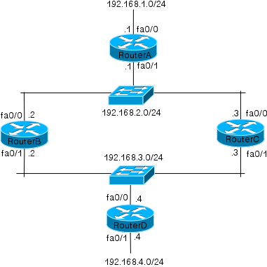
The network shown in Figure 5-2 will be used for the rest of the RIP sections.
Now that you know how RIP works and how to configure it, let us configure the network shown in Figure 5-2 to see effect of RIP on the routing table. For this example, we will enable RIP on RouterA, RouterB and RouterD only. RouterC will be configured in one of the sections ahead. The configuration required on the three routers is shown below:
RouterA(config)#router rip
RouterA(config-router)#network 192.168.1.0
RouterA(config-router)#network 192.168.2.0
RouterB(config)#router rip
RouterB(config-router)#network 192.168.2.0
RouterB(config-router)#network 192.168.3.0
RouterD(config)#router rip
RouterD(config-router)#network 192.168.3.0
RouterD(config-router)#network 192.168.4.0
Figure 5-2 RIP example
Now take a look at the routing table on each of the three routers to see the effect:
RouterA#sh ip route
–output truncated–
Gateway of last resort is not set
R 192.168.4.0/24 [120/2] via 192.168.2.2, 00:00:25, FastEthernet0/1
C 192.168.1.0/24 is directly connected, FastEthernet0/0
C 192.168.2.0/24 is directly connected, FastEthernet0/1
R 192.168.3.0/24 [120/1] via 192.168.2.2, 00:00:25, FastEthernet0/1
RouterB#sh ip route
–output truncated–
Gateway of last resort is not set
R 192.168.4.0/24 [120/1] via 192.168.3.4, 00:00:19, FastEthernet0/1
R 192.168.1.0/24 [120/1] via 192.168.2.1, 00:00:15, FastEthernet0/0
C 192.168.2.0/24 is directly connected, FastEthernet0/0
C 192.168.3.0/24 is directly connected, FastEthernet0/1
RouterD#sh ip route
–output truncated–
Gateway of last resort is not set
C 192.168.4.0/24 is directly connected, FastEthernet0/1
R 192.168.1.0/24 [120/2] via 192.168.3.2, 00:00:23, FastEthernet0/0
R 192.168.2.0/24 [120/1] via 192.168.3.2, 00:00:23, FastEthernet0/0
C 192.168.3.0/24 is directly connected, FastEthernet0/0
In the above output, note the lines that start with R. The R signifies that these routes were learned from RIP. In output from RouterA, notice that the route to 192.168.4.0/24 network was learned from RIP. The 120/2 in the line shows that the administrative distance of the route is 120 (default RIP AD) and that the destination network is two hops away. The next hop towards 192.168.4.0/24 is 192.168.2.2, which is RouterB. Similarly you will notice that each router now knows about every subnet in the network. You may have noticed that compared to static or default routing, configuring RIP was easier and faster. Now when there is a change in the network, the routing table will automatically get updated across the network.
RIP version 2 (RIPv2)
RIPv1 was one of the earliest routing protocols and was very popular back when it was created. With evolution in networking standards, RIP was found lacking in many places. Hence RIPv2 was developed in 1993 and standardized under RFC 2453. While RIPv2 is also a distance-vector routing protocols and fundamentally similar to RIPv1, there are some difference in the way it works. Table 5-1 shows the differences between RIPv1 and RIPv2.
Table 5-1 Differences between RIPv1 and RIPv2
|
RIPv1 |
RIPv2 |
| It is a classful protocol and does not send subnet masks in routing updates | Is a classless protocol and sends subnet masks in routing updates |
| Uses broadcast to communicate with neighbors | Uses multicast to communicate with peers. Multicast address 224.0.0.9 is used. |
| RIPv1 does not support authentication | RIPv2 supports authentication |
| Does not support VLSM | Supports VLSM |
Remember that apart from the differences given in Table 5-1, RIPv2 is similar to RIPv1 with a maximum hop count of 15 and same timers as RIPv1. It also implements the same loop prevention techniques as RIPv1. The configuration for RIPv2 is same as RIPv1 but requires the addition of version 2 command in the routing configuration mode. RouterA, RouterB and RouterD from our previous example can be configured to use RIPv2 as shown below:
RouterA(config)#router rip
RouterA(config-router)#version 2
RouterB(config)#router rip
RouterB(config-router)#version 2
RouterD(config)#router rip
RouterD(config-router)#version 2
Take a look at the routing tables of these routers after the change:
RouterA#sh ip route
–output truncated–
Gateway of last resort is not set
R 192.168.4.0/24 [120/2] via 192.168.2.2, 00:00:11, FastEthernet0/1
C 192.168.1.0/24 is directly connected, FastEthernet0/0
C 192.168.2.0/24 is directly connected, FastEthernet0/1
R 192.168.3.0/24 [120/1] via 192.168.2.2, 00:00:11, FastEthernet0/1
RouterB#sh ip route
–output truncated–
Gateway of last resort is not set
R 192.168.4.0/24 [120/1] via 192.168.3.4, 00:00:20, FastEthernet0/1
R 192.168.1.0/24 [120/1] via 192.168.2.1, 00:00:05, FastEthernet0/0
C 192.168.2.0/24 is directly connected, FastEthernet0/0
C 192.168.3.0/24 is directly connected, FastEthernet0/1
RouterD#sh ip route
–output truncated–
Gateway of last resort is not set
C 192.168.4.0/24 is directly connected, FastEthernet0/1
R 192.168.1.0/24 [120/2] via 192.168.3.2, 00:00:07, FastEthernet0/0
R 192.168.2.0/24 [120/1] via 192.168.3.2, 00:00:07, FastEthernet0/0
C 192.168.3.0/24 is directly connected, FastEthernet0/0
You will notice that the routing table output is same irrespective of the RIP version used. The output will only differ between the two protocols if the default mask is not used for the given class. In such a case, you will notice that when RIPv2 is used, the subnet mask is correctly seen on the neighbor while in case of RIPv1 the neighbor assumes the default subnet mask. To show this difference in the routing table, I temporarily added a 192.168.20.0/25 network on RouterA and advertised it using RIPv1. The output of the routing table from RouterB is shown below:
RouterB#sh ip route
–output truncated–
Gateway of last resort is not set
R 192.168.4.0/24 [120/1] via 192.168.3.4, 00:00:00, FastEthernet0/1
R 192.168.20.0/24 [120/1] via 192.168.2.1, 00:00:11, FastEthernet0/0
R 192.168.1.0/24 [120/1] via 192.168.2.1, 00:00:11, FastEthernet0/0
C 192.168.2.0/24 is directly connected, FastEthernet0/0
C 192.168.3.0/24 is directly connected, FastEthernet0/1
In the above output notice that the route to 192.168.20.0 network has a mask of /24 instead of /25. When the version was changed to 2, notice the routing table output on RouterB:
RouterB#sh ip route
–output truncated–
Gateway of last resort is not set
R 192.168.4.0/24 [120/1] via 192.168.3.4, 00:00:03, FastEthernet0/1
192.168.20.0/25 is subnetted, 1 subnets
R 192.168.20.0 [120/1] via 192.168.2.1, 00:00:03, FastEthernet0/0
R 192.168.1.0/24 [120/1] via 192.168.2.1, 00:00:03, FastEthernet0/0
C 192.168.2.0/24 is directly connected, FastEthernet0/0
C 192.168.3.0/24 is directly connected, FastEthernet0/1
Notice that the mask for the 192.168.20.0 is correct displayed at /25 when RIPv2 was used.
Stopping RIP updates on an Interface
As soon as RIP is enabled, it will start sending and receiving updates on interfaces. Many situations require you to stop RIP from sending updates out an interface. An example of such a situation is when an interface connects to the Internet. You do not want your routing updates to go out to the Internet. In such situations, you can use the passive-interface interface command in the routing configuration mode to stop RIP from sending updates out that interface. This command stop RIP from sending updates but it will continue to receive updates on that interface.
In our example network, we do not need to send RIP updates out interface fa0/0 on RouterA and interface fa0/1 on RouterD. We can stop updates going of of these interfaces using the following commands:
RouterA(config)#router rip
RouterA(config-router)#passive-interface fa0/0
RouterD(config)#router rip
RouterD(config-router)#passive-interface fa0/1
RIP load balancing
Remember that we did not configure RouterC earlier? Let us configure RouterC to run RIP across both its networks as shown below:
RouterC(config-router)#network 192.168.2.0
RouterC(config-router)#network 192.168.3.0
After the above configuration, the routing table on RouterC looks as shown below:
RouterC#sh ip route
–output truncated–
Gateway of last resort is not set
R 192.168.4.0/24 [120/1] via 192.168.3.4, 00:00:16, FastEthernet0/1
R 192.168.1.0/24 [120/1] via 192.168.2.1, 00:00:11, FastEthernet0/0
C 192.168.2.0/24 is directly connected, FastEthernet0/0
C 192.168.3.0/24 is directly connected, FastEthernet0/1
The output above is similar to what was seen in RouterB. So why did we not configure RotuerC earlier? Take a look at the routing table of RouterA after we enabled RIP on RouterC:
RouterA#sh ip route
–output truncated–
Gateway of last resort is not set
R 192.168.4.0/24 [120/2] via 192.168.2.3, 00:00:18, FastEthernet0/1
[120/2] via 192.168.2.2, 00:00:10, FastEthernet0/1
C 192.168.1.0/24 is directly connected, FastEthernet0/0
C 192.168.2.0/24 is directly connected, FastEthernet0/1
R 192.168.3.0/24 [120/1] via 192.168.2.3, 00:00:18, FastEthernet0/1
[120/1] via 192.168.2.2, 00:00:10, FastEthernet0/1
In the above output notice that RouterA’s routing table has two paths listed to 192.168.4.0/24 and 192.168.3.0/24. Similarly, RouterD has two paths listed for 192.168.1.0/24 and 192.168.2.0/24 as shown below:
RouterD#sh ip route
–output truncated–
Gateway of last resort is not set
C 192.168.4.0/24 is directly connected, FastEthernet0/1
R 192.168.1.0/24 [120/2] via 192.168.3.3, 00:00:07, FastEthernet0/0
[120/2] via 192.168.3.2, 00:00:05, FastEthernet0/0
R 192.168.2.0/24 [120/1] via 192.168.3.3, 00:00:07, FastEthernet0/0
[120/1] via 192.168.3.2, 00:00:05, FastEthernet0/0
C 192.168.3.0/24 is directly connected, FastEthernet0/0
To explain this behavior, consider what happened when RouterC started advertising its routes to RouterA and RouterD. Till that point, RouterA has only one way to reach 192.168.3.0/24 and 192.168.4.0/24 with hop counts of 1 and 2 respectively. When RouterC advertised its routes to RouterA, it also advertised the networks 192.168.3.0/24 and 192.168.4.0/24 with hop counts of 1 and 2. At this stage, RouterA has two paths to the same destination and both paths have the same metric. As you already know, when a routing protocol has multiple paths to a destination it compares the metric to decide which path to use. In this same we have two equal cost paths. When a routing protocol has two or more equal cost paths, it will use both the paths and the traffic will be load balanced across both the paths. Hence in the above outputs you see two paths for the destination networks.
RIP can load balance between 4 equal cost paths by default. The older codes of Cisco IOS support load balancing across a maximum of 6 equal cost paths while the newer codes support load balancing across a maximum of 16 equal cost paths. You can change the default value of 4 using the maximum-paths number under the routing configuration mode.