This will be a good time to introduce you to another very significant change that Cisco made to STP. Before that, note that this section discusses VLANs. For now remember that VLANs provide different broadcast domains at layer 2 and hence keep traffic from one subnet different from another. We will cover VLANs in more detail in Chapter 7.
When IEEE 802.1d was drafted, VLANs did not exist. Hence one Spanning Tree instance worked across the entire switch. Eventually VLANs were introduced and they created different networks on the same switch. This gave rise to need to have different topology for load balancing and flexible Spanning Trees. The need for Per VLAN STP can be further understood from the network shown in Figure 6-13.
Figure 6-13 Per-VLAN STP
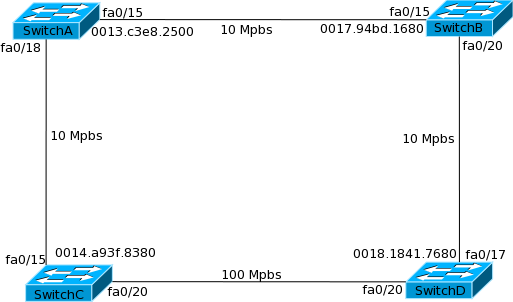
SwitchD has two ways to paths to reach SwitchA. In any implementation of STP (Per-VLAN or a single STP), one of the interfaces will be blocked. Let us assume that fa0/17 is blocked in this network. This works well in an environment where the whole network is one single big network. Now consider a situation where the network is divided into two smaller networks using VLANs. If both the VLANs spanned all the four switches, would it not be useful to have fa0/17 blocked for one VLAN and fa0/20 blocked for the other VLAN? This way traffic in both VLANs can be load balanced across both paths!
To achieve this, Cisco added the Per-VLAN Spanning Tree Plus (PVST+) feature on its switches. With this feature, Cisco switches ran one STP instance for every VLAN.
When IEEE introduced 802.1w it still did not accommodate multiple Spanning Tree instances on a switch. Cisco introduced the Per-VLAN Rapid Spanning Tree (PVRST) to support Rapid Spanning Tree instances on each VLAN on the switch. PVST+ and PVRST both provide the same functionality across both 802.1D and 802.1w standards.
Remember that PVST+ and PVRST both add the VLAN number to the bridge ID of every switch. That is the reason you earlier saw the priority as 8197 in VLAN 5 even though you had configured the priority as 8192.
To enable RSTP for each VLAN in our switched network, we use the following command:
This is all that is needed if we need only instance of the spanning tree protocol. Later on in this section, we will show what is needed to enable the load sharing capabilities.
Using the “show spanning-tree vlan <vlan#>” command, we can verify which type of spanning tree is running.
Switch#show spanning-tree vlan 10
VLAN0010
Spanning tree enabled protocol rstp
Root ID Priority 24586
Address 0015.63f6.b700
Cost 3019
Port 107 (FastEthernet3/0/1)
Hello Time 2 sec Max Age 20 sec Forward Delay 15 sec
Bridge ID Priority 49162 (priority 49152 sys-id-ext 10)
Address 000f.f794.3d00
Hello Time 2 sec Max Age 20 sec Forward Delay 15 sec
–output truncated—
Two items are of interest in this output. First is the Spanning Tree Protocol – RSTP and the second is the “sys-id-ext 10”. This shows that the Bridge priority was configured as 49152 and VLAN id 10 was added to it.
How can load balancing be achieved in the network shown in Figure 6-13 if VLAN 1 and VLAN 5 are being used on the LAN? We can achieve it by configuring Switch A with a better priority for VLAN 1 and configuring SwitchB with a better priority for VLAN 5. This can be done using the following commands:
SwitchA(config)#spanning-tree vlan 1 priority 4096
SwitchB(config)#spanning-tree vlan 5 priority 4096
Let’s see the “show spanning-tree” output for both VLANs on SwitchD to verify loadbalancing.
SwitchD#show spanning-tree vlan 1
VLAN0001
Spanning tree enabled protocol rstp
Root ID Priority 4097
Address 0013.c3e8.2500
–output truncated–
Interface Role Sts Cost Prio.Nbr Type
——————- —- — ——— ——– ——————————–
Fa0/17 Desg FWD 119 128.17 P2p
Fa0/20 Root FWD 19 128.20 P2p
SwitchD#show spanning-tree vlan 5
VLAN0005
Spanning tree enabled protocol rstp
Root ID Priority 4101
Address 0017.94bd.1680
–output truncated–
Interface Role Sts Cost Prio.Nbr Type
——————- —- — ——— ——– ——————————–
Fa0/17 Root FWD 19 128.17 P2p
Fa0/20 Desg FWD 119 128.20 P2p
We can see that the root bridge for VLAN1 is SwitchA whereas the root bridge for VLAN5 is SwitchB. Fa0/20 is the Root port for VLAN 1 and Fa0/17 is the root port for VLAN 5.