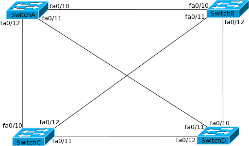
Figure 6-8 shows a full mesh network. A good redundant setup where, if one link fails, there would be two more links for traffic to go through. However, could this lead to any problems? Let’s say a host is connected to port fa0/1 on SwitchA (not shown) and this switch sends a broadcast out to the network. SwitchA has to forward this frame out every port except fa0/1. A part of what happens next is shown below:
- SwitchB receives the packet on fa0/10 and sends it out on every port except that one.
- SwitchD receives the packet on fa0/10 and sends it out on every port except that one but including fa0/11.
- SwitchA receives the packet on fa0/11 and sends it out on every port except fa0/11 but including fa0/1 and fa0/10!
What we see here is that not only the original source received the frame back but now SwitchA has to send the packet back out fa0/10 also. Back to the step one to three which goes on forever.
Figure 6-8 Full mesh switched network
As you already know, what we have just seen is a loop and such loops can bring a network to a grinding halt. Layer 2 LAN protocols have no method to stop traffic endlessly travelling around possibly carrying inaccurate information. At layer 3 we can make packets expire after a certain amount of time or after they have traveled a certain distance (using route poisoning for example – see the routing module for more info).
As layer 2 networks grew, it quickly became evident that a system to prevent loops was needed if LANs were to continue to function. Digital Equipment Corporation created a protocol called Spanning Tree Protocol (STP) to prevent broadcast storms and network loops at layer 2. The IEEE under standard 802.1d now regulates STP.
STP allows bridges and switches to communicate with each other so they can create a loop free topology. Each bridge runs the Spanning Tree Algorithm that calculates how a loop can be prevented. When STP is applied to a looped LAN topology, all segments will be reachable but any open ports that would create a traffic loop are blocked. When it sees a loop in the network it blocks one or more redundant paths preventing a loop from forming. STP continually monitors the network always looking for failures on switch ports or changes in the network topology. If a change on the LAN is detected, STP can quickly make redundant ports available and close other ports to ensure the network continues to function normally.
Before we learn further about STP, we need to understand some of the common terms associated with it.
Bridge ID: This is a unique identification number of each switch in the network. It consists of bridge priority and the base MAC Address of the switch. The default bridge priority of a Cisco Switch is 32768. This is a configurable value between 0 to 61440 but the value has to be in increments of 4096. 4096, 8192, 12288, so on and so forth are acceptable values. Priority plays a very big role in STP and how well the network will function.
Root Bridge: All switches in the network elect the root of the tree. Thereon all decisions such as which redundant path to block and which to open are taken from the perspective of the root switch (commonly called the Root Bridge). The switch with the lowest Bridge ID wins the election. Switches that do not become Root Bridge are called NonRoot Bridges.
BPDU: Bridge Protocol Data Unit (BPDU) is the information exchanged between switches to select the Root Bridge as well as configure the network after that. A decision on which port to block is taken after examining BPDUs from the neighbors. Cisco Switches send BPDUs every 2 seconds by default. This value can be configured from 1 second to 10 seconds.
Root Port: Each switch has to have a path to the Root Bridge, if not directly connected. Root port is the directly connected link or the fastest path to the Root Bridge from a NonRoot bridge.
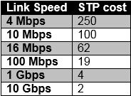
Port Cost: Each port has a cost that is determined by the bandwidth of the link. Port cost determines which of the redundant links will not be blocked. The lower the cost, the better it is. Port Cost also determines which port will become the root port if multiple paths to the root bridge exist. Default port costs are shown below.
Table 6-1 Default STP cost
Designated Port: The bridges on a network segment collectively determine which bridge has the least-cost path from the network segment to the root. The port connecting this bridge to the network segment is then the designated port for the segment. Ports that are not selected Designated Ports are called Non-Designated Ports.
Port States in Spanning Tree
Switch ports running STP can be in one of five states.
- Blocked
- Listening
- Learning
- Forwarding
- Disabled
STP port states are very important. You should remember these states and what they mean. Each of them is discussed below.
Blocked
None of the ports will transmit or receive any data, but they will listen to BPDUs. The BPDU carries various pieces of information that are used by STP to determine what state the ports should be in and what the STP topology should be.
Listening
The switch listens for frames but doesn’t learn or act on them. The switch does receive the frames but discards them before any action is taken. MAC addresses are not placed into the CAM table while the port is listening.
Learning
The switch will start to learn MAC addresses it can see and will populate its CAM table with the addresses and the ports on which they were found. In this state, the switch will start to transmit its own BPDUs.
Forwarding
The switch has learned MAC addresses and corresponding ports and populates its CAM table with this. The switch can now forward traffic.
Disabled
In the Disabled state, the port will receive BPDUs but will not forward them to the switch processor. It discards all incoming frames from both the port and other forwarding ports on the switch.
The port states are transitional and allow other BPDUs to arrive in good time from other switches. Port transition times are typically:
- Initialization to blocking
- Blocking to listening (20 secs)
- Listening to learning (15 secs)
- Learning to forwarding (15 secs)
- Forwarding to disabled (if there is a failure)
All ports start at the blocking state (there are a few exceptions discussed later). After STP convergence, some ports will transition to listening, learning, and finally forwarding while the rest would remain in a blocked state. Thus the time needed to transition from one stage to another; we find that a layer 2 network running STP takes 50 seconds to start switching data! This is known as the convergence time.
STP Convergence
Remember that Spanning tree works by selecting a root bridge on the LAN. It is selected by comparing Bridge ID of each switch.
STP is be considered to be converged after three steps have taken place:
- Elect root bridge
- Elect root ports
- Elect designated ports
Each of the above three steps are discussed in detail below. The network shown in figure 6-9 will be used to explain the STP convergence process.
Elect Root Bridge
The bridge with the lowest Bridge ID (BID) becomes the root bridge. The BID consists of two values in an 8-byte field. The bridge priority (32,768 by default) makes up two bytes and the MAC address of the backplane or supervisor module (depending upon the model of switch) makes up the rest of the six bytes.
The root bridge on a LAN is selected by an election. Each switch running STP passes information in a format known as bridge protocol data units (BPDUs). BPDUs are multicast frames that can be thought of as hello messages between STP enabled switches and they are sent out every two seconds from every port. This is necessary to maintain a loop free topology. When the switch or bridge priorities combined with its MAC address are all exchanged; the bridge with the lowest ID is selected as the root bridge.
Figure 6-9 STP Convergence

All ports on the root bridge are set as designated and thus are always set to a forwarding state.
In our network, the priority of all the switches has been left at the default value. So the switch with the lowest MAC address will be selected the root bridge. In this case it will be SwitchA.
To verify this we issue the “show spanning tree vlan (vlan#)” command on SwitchA :
SwitchA#show spanning-tree vlan 5
VLAN0005
Spanning tree enabled protocol ieee
Root ID Priority 32773
Address 0013.c3e8.2500
This bridge is the root
Hello Time 2 sec Max Age 20 sec Forward Delay 15 sec
Bridge ID Priority 32773 (priority 32768 sys-id-ext 5)
Address 0013.c3e8.2500
Hello Time 2 sec Max Age 20 sec Forward Delay 15 sec
Aging Time 300
Interface Role Sts Cost Prio.Nbr Type
——————- —- — ——— ——– ——————————–
Fa0/15 Desg FWD 19 128.15 P2p
Fa0/18 Desg FWD 19 128.18 P2p
In the above output notice that the fourth line states that this bridge is the root bridge. At this stage do not worry about the number 5 used in the command. That is the VLAN id and will be discussed in chapter 7.
Now if we want SwitchC to be the root bridge then we will need to give it better priority using the following command:
Let’s check the “show spanning-tree” output now on SwitchC and SwitchA
SwitchC#show spanning-tree vlan 5
VLAN0005
Spanning tree enabled protocol ieee
Root ID Priority 8197
Address 0014.a93f.8380
This bridge is the root
Hello Time 2 sec Max Age 20 sec Forward Delay 15 sec
Bridge ID Priority 8197 (priority 8192 sys-id-ext 5)
Address 0014.a93f.8380
Hello Time 2 sec Max Age 20 sec Forward Delay 15 sec
Aging Time 300
SwitchA#show spanning-tree vlan 5
VLAN0005
Spanning tree enabled protocol ieee
Root ID Priority 8197
Address 0014.a93f.8380
Cost 19
Port 18 (FastEthernet0/18)
Hello Time 2 sec Max Age 20 sec Forward Delay 15 sec
Bridge ID Priority 32773 (priority 32768 sys-id-ext 5)
Address 0013.c3e8.2500
Hello Time 2 sec Max Age 20 sec Forward Delay 15 sec
Aging Time 300
In the above output notice that:
- SwitchC shows it is the root bridge now.
- SwitchA shows the MAC address of SwitchC as that of the root bridge along with the new priority of SwitchC.
In case you are wondering why SwitchC’s priority is 8197 instead of 8192, we will come to this point shortly. Let’s set the priority on SwitchC back to 32768 and make SwitchA the root bridge for the following sections.
Elect Root Ports
For non-root bridges there will be only one root port. The root port will be the port with the lowest path cost to the root bridge. The root port will also be set to forwarding state.
Path cost is the cost of transmitting a frame to the root bridge. The value is set according to the bandwidth of the link on the LAN. The slower the link, the higher the cost is.
In our network, SwitchB and SwitchC’s fa0/15 ports will be the root ports because they are directly connected to SwitchA.
Switch D has two options – fa0/17 towards SwitchB and fa0/20 towards SwitchC. The total cost of the link on fa0/17 is 200 (2×10 Mbps = 100×2). The total cost of the link on fa0/20 is 119 (10 Mbps = 100 and 100 Mbps = 19). So fa0/20 will be the root port for SwitchD and fa0/17 will be blocked. Remember that a default cost is associated with the bandwidth of a link. The default cost can be seen in table 6-1.
Let us verify SwitchD’s root port using the “show spanning-tree” command:
SwitchD#show spanning-tree vlan 5
VLAN0005
Spanning tree enabled protocol ieee
Root ID Priority 32773
Address 0013.c3e8.2500
Cost 23
Port 20 (FastEhternet0/20)
Hello Time 2 sec Max Age 20 sec Forward Delay 15 sec
Bridge ID Priority 32773 (priority 32768 sys-id-ext 5)
Address 0018.1841.7680
Hello Time 2 sec Max Age 20 sec Forward Delay 15 sec
Aging Time 300
Interface Role Sts Cost Prio.Nbr Type
——————- —- — ——— ——– ——————————–
fa0/17 Altn BLK 200 128.17 P2p
fa0/20 Root FWD 119 128.20 P2p
Notice that the role for interface fa0/20 is shown as Root while the status is forwarding. On the other hand, fa0/17 is in the blocked state.
If we want to make fa0/17 on SwitchD as a root port instead of fa0/20, then we will need to change the cost on fa0/17 to something better (less) than 119. To do this, the “spanning-tree cost” command can be used on fa0/17. Look at the following output
SwitchD(config)#int fa0/17
SwitchD(config-if)#spanning-tree cost 1
SwitchD(config-if)#do show spanning-tree vlan
–output truncated–
Interface Role Sts Cost Prio.Nbr Type
——————- —- — ——— ——– ——-
fa0/17 Root LIS 1 128.17 P2p
fa0/20 Altn BLK 119 128.20 P2p
In the above output notice that on changing the cost of interface fa0/17, it has become the Root port and is transitioning from Blocked to forwarding state while fa0/20 is now in the blocked state.
Elect Designated Ports
If a switch has redundant ports connecting it to a LAN segment (another downstream switch or hub for example) then the port with the lowest cost will be elected the designated port. Designated ports forward BPDUs into the LAN segment and traffic to and from the LAN segment. In simple terms the designated port becomes the only link for the LAN segment towards the rest of the network and the root bridge.
In our example fa0/20 port on SwitchC will be the designated port for the link to SwitchD. If there were multiple links then an election would have taken place. Let us verify this on SwitchC:
SwitchC#show spanning-tree vlan 5
VLAN0005
Spanning tree enabled protocol ieee
Root ID Priority 32773
Address 0013.c3e8.2500
Cost 19
Port 15 (Fasthernet0/15)
Hello Time 2 sec Max Age 20 sec Forward Delay 15 sec
Bridge ID Priority 32773 (priority 32768 sys-id-ext 5)
Address 0014.a93f.8380
Hello Time 2 sec Max Age 20 sec Forward Delay 15 sec
Aging Time 300
Interface Role Sts Cost Prio.Nbr Type
——————- —- — ——— ——– ——————————–
fa0/15 Root FWD 100 128.15 P2p
fa0/20 Desg FWD 19 128.20 P2p
Notice that fa0/20 has a role of designated port with state as forwarding. The election of designated port can be influence by changing the cost of the port This concludes a basic overview of STP. STP can be difficult to understand and the following sections look deeper into various aspects of it. Hence, I strongly suggest you take a break and re-read this section to get a firm grasp of STP before continuing.