By default, a host can communicate with only those hosts that are members of the same VLAN. In order to change this default behavior and allow communication between different VLANs, you need a router or a layer 3 switch. We will learn both approaches starting with the router approach.
The router has to support ISL or 802.1Q trunking on a FastEthernet or GigabitEthernet interface in order to perform routing between different VLANs. The router’s interface is divided into logical interfaces called subinterfaces, one for each VLAN. From a FastEthernet or GigabitEthernet interface on the router, you can set the interface to perform trunking with the encapsulation command:
R1>enable
R1#configure terminal
Enter configuration commands, one per line. End with CNTL/Z.
R1(config)#interface FastEthernet0/0.10
R1(config-subif)#encapsulation ?
dot1Q IEEE 802.1Q Virtual LAN
R1(config-subif)#encapsulation dot1Q ?
<1-4094> IEEE 802.1Q VLAN ID
R1(config-subif)#encapsulation dot1Q 10
Please note that the Cisco 2811 router named R1 supports only 802.1Q trunking. As we learned earlier in the chapter that Cisco is moving away from ISL and newer hardware like the Cisco 2800 series Integrated Services Router (ISR) does not even support ISL.
We have used subinterface number 10 which happens to be the same as the VLAN ID associated with the subinterface. It is common practice to make the subinterface number match the VLAN ID which makes the configuration more predictable and helps in configuration and troubleshooting. But it is just an arbitration and subinterface number and VLAN ID don’t have to necessarily match. Remember that the subinterface number is only locally significant, and it does not matter which subinterface numbers are configured on the router.
Another important fact about VLANs is that each VLAN also is a separate IP subnet. Although it is not an absolute requirement to have a one-to-one mapping between VLANs and IP subnets but it really is a good idea to configure your VLANs as separate subnets, so better stick to this best practice.
In order to make sure you are fully prepared to configure inter-VLAN routing, we will go through two different configuration examples in detail.
Let’s start by looking at the figure that follows and reading the router and switch configuration given for the figure.
Figure 7-11 Inter-VLAN Routing Example1
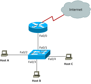
The switch interfaces have the following roles:
Fa0/2, Fa0/3: VLAN 10
Fa0/4: VLAN 20
On the router, you create two subinterfaces one for each VLAN matching the subinterface number with the VLAN ID associated with the subinterface. Each VLAN has its own IP subnet and the IP addresses are configured for subinterfaces. Notice that we did not configure any IP address for the physical interface on the router. This is standard router-on-a-stick configuration for inter-VLAN routing:
Enter configuration commands, one per line. End with CNTL/Z.
R1(config)#interface Fa0/0.10
R1(config-subif)#encapsulation dot1q 10
R1(config-subif)#ip address 192.168.10.1 255.255.255.0
R1(config-subif)#interface Fa0/0.20
R1(config-subif)#encapsulation dot1q 20
R1(config-subif)#ip address 192.168.20.1 255.255.255.0
Having come this far in your CCNA studies, you should be able to figure out which IP subnets are being used by looking at the router configuration. You can see that we are using 192.168.10.0/24 with VLAN 10 and 192.168.20.0/24 with VLAN 20. And by looking at the switch configuration, you can see that interfaces FastEthernet0/2 and FastEthernet0/3 are in VLAN 10 and interface FastEthernet0/4 is in VLAN 20. This means that Host A and Host B are in VLAN 10 and Host C is in VLAN 20.
SW1#conf term
Enter configuration commands, one per line. End with CNTL/Z.
SW1(config)#interface Fa0/2
SW1(config-if)#switchport access vlan 10
SW1(config-if)#switchport mode access
SW1(config-if)#interface Fa0/3
SW1(config-if)#switchport access vlan 10
SW1(config-if)#switchport mode access
SW1(config-if)#interface Fa0/4
SW1(config-if)#switchport access vlan 20
SW1(config-if)#switchport mode access
We are configuring the IP addresses on hosts manually or statically as below:
Host A
IP Address 192.168.10.2
Subnet Mask 255.255.255.0
Default Gateway 192.168.10.1
Host B
IP Address 192.168.10.3
Subnet Mask 255.255.255.0
Default Gateway 192.168.10.1
Host C
IP Address 192.168.20.2
Subnet Mask 255.255.255.0
Default Gateway 192.168.20.1
The hosts can have any IP address in the subnet range but I just chose the first available IP addresses after the default gateway address to make the configuration simpler and predictable. Always keep in mind that easier to read and predict configurations are always easier to maintain and troubleshoot as well from a practical standpoint.
Now again using the figure as reference, let’s go through the commands necessary to configure switch interface Fa0/1 to establish a link with the router and provide inter-VLAN communication using IEEE 802.1q encapsulation. Please note that I have used a Cisco 3560 switch here and the commands can vary slightly depending on what switch model you are working with.
Enter configuration commands, one per line. End with CNTL/Z.
SW1(config)#interface fa0/1
SW1(config-if)#switchport trunk encapsulation ?
dot1q Interface uses only 802.1q trunking encapsulation when trunking
isl Interface uses only ISL trunking encapsulation when trunking
negotiate Device will negotiate trunking encapsulation with peer on
interface
SW1(config-if)#switchport trunk encapsulation dot1q
SW1(config-if)#switchport mode trunk
As you can see, our Cisco 3560 switch supports both IEEE 802.1Q and ISL encapsulation in addition to negotiate mode that allows encapsulation to be negotiated through
dynamic Trunking Protocol (DTP). We specified 802.1Q as the trunking protocol in order to successfully perform trunking with the router. Also keep in mind that when we create a trunk link like the one we just created, all VLANs 1 to 4094 are allowed to pass data by default. However, it is possible to allow only a subset of the range of VLANs while blocking others.
Let’s move on to our second and final configuration example for inter-VLAN routing involving a somewhat more complex scenario as shown in the figure below:
Figure 7-12 Inter-VLAN Routing Example 2
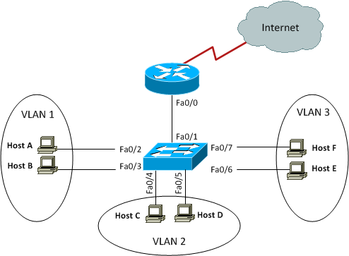
This figure shows three VLANs 1, 2, and 3 with two hosts in each of them. The router is connected to the switch using subinterfaces on port Fa0/1 on the switch. The switch port connecting to the router is a trunk port. The switch ports connecting to the clients are all access ports, not trunk ports. The configuration of the switch would look something like this:
SW1#conf term
Enter configuration commands, one per line. End with CNTL/Z.
SW1(config)#interface fa0/1
SW1(config-if)#switchport mode trunk
SW1(config-if)#int fa0/2
SW1(config-if)#switchport access vlan 1
SW1(config-if)#switchport mode access
SW1(config-if)#int fa0/3
SW1(config-if)#switchport access vlan 1
SW1(config-if)#switchport mode access
SW1(config-if)#int fa0/4
SW1(config-if)#switchport access vlan 2
SW1(config-if)#switchport mode access
SW1(config-if)#int fa0/5
SW1(config-if)#switchport access vlan 2
SW1(config-if)#switchport mode access
SW1(config-if)#int fa0/6
SW1(config-if)#switchport access vlan 3
SW1(config-if)#switchport mode access
SW1(config-if)#int fa0/7
SW1(config-if)#switchport access vlan 3
SW1(config-if)#switchport mode access
Before we configure the router, we need to know the IP subnets assigned to VLANs:
VLAN 2: 172.16.1.32/28
VLAN 3: 172.16.1.48/28
The configuration of the router would then look something like this:
R1#conf term
Enter configuration commands, one per line. End with CNTL/Z.
R1(config)#int fa0/0
R1(config-if)#no ip address
R1(config-if)#no shutdown
R1(config-if)#int fa0/0.1
R1(config-subif)#encapsulation dot1q 1
R1(config-subif)#ip address 172.16.1.17 255.255.255.240
R1(config-subif)#int fa0/0.2
R1(config-subif)#encapsulation dot1q 2
R1(config-subif)#ip address 172.16.1.33 255.255.255.240
R1(config-subif)#int fa0/0.3
R1(config-subif)#encapsulation dot1q 3
R1(config-subif)#ip address 172.16.1.49 255.255.255.240
The hosts in each VLAN would be assigned an IP address from the IP subnets associated with the VLAN, and the default gateway would be the IP address assigned to the
outer’s subinterface in that VLAN.
VTP Configuration
In this section, we will configure VLAN Trunking Protocol (VTP) for the switched network shown in the diagram:
Figure 7-13 VTP Configuration Example
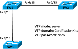
Cisco switches are configured to be in VTP server mode by default. The first step in configuring VTP would be to set the VTP domain name you want to use. VTP domain name can be any string of characters which must be configured on all switches that are to exchange VLAN information over VTP with each other.
When you create the VTP domain, there are quite a few options you can set including the domain name, password, mode, and pruning. You can set all of these options using the vtp command in global configuration mode. In the following example, we will set switch SW1 to VTP server mode, the VTP domain to CertificationKits, and the VTP password to cisco:
Enter configuration commands, one per line. End with CNTL/Z.
SW1(config)#vtp mode server
Device mode already VTP SERVER.
SW1(config)#vtp domain CertificationKits
Changing VTP domain name from null to CertificationKits
SW1(config)#vtp password cisco
Setting device VLAN database password to cisco
SW1(config)#exit
SW1#
We are done with configuring various VTP options but we have to find a way to verify that configuration. There are two very useful commands to verify VTP configuration and they are show vtp status and show vtp password:
VTP Version : running VTP1 (VTP2 capable)
Configuration Revision : 0
Maximum VLANs supported locally : 1005
Number of existing VLANs : 9
VTP Operating Mode : Server
VTP Domain Name : CertificationKits
VTP Pruning Mode : Disabled
VTP V2 Mode : Disabled
VTP Traps Generation : Disabled
MD5 digest : 0x60 0xDE 0xD6 0xAC 0x3F 0x23 0xF6 0xC6
Configuration last modified by 10.0.1.1 at 3-1-93 02:07:25
Local updater ID is 0.0.0.0 (no valid interface found)
SW1#show vtp password
VTP Password: cisco
SW1#
The preceding output shows that VTP mode, domain name, and password have been successfully configured. You may recall that all switches are in VTP server mode by default, and you actually have to be in VTP server mode if you want to change any VLAN information on the switch.
Let’s now go to switches SW2 and SW3 and set them into the CertificationKits VTP domain. It is very important to keep in mind that the VTP domain name is case sensitive.
Enter configuration commands, one per line. End with CNTL/Z.
SW2(config)#vtp mode client
Setting device to VTP CLIENT mode.
SW2(config)#vtp domain CertificationKits
Changing VTP domain name from null to CertificationKits
SW2(config)#vtp password cisco
Setting device VLAN database password to cisco
SW2(config)#exit
SW2#show vtp status
VTP Version : running VTP1 (VTP2 capable)
Configuration Revision : 0
Maximum VLANs supported locally : 1005
Number of existing VLANs : 9
VTP Operating Mode : Client
VTP Domain Name : CertificationKits
VTP Pruning Mode : Disabled
VTP V2 Mode : Disabled
VTP Traps Generation : Disabled
MD5 digest : 0x60 0xDE 0xD6 0xAC 0x3F 0x23 0xF6
0xC6
Configuration last modified by 10.0.1.1 at 3-1-93 02:07:25
Local updater ID is 0.0.0.0 (no valid interface found)
SW2#show vtp password
VTP Password: cisco
SW2#
You can repeat the same configuration on SW3 to complete the configuration on all three switches. Now that all our switches are set to the same VTP domain and password, it’s time to test if our VTP configuration achieves what it is supposed to achieve. You may recall that the primary goal of VTP is to be able to create VLANs only on the VTP server and let that VLAN information propagate to VTP clients through VTP advertisements. We created a few VLANs on SW1 earlier and they should be advertised to the VTP client switches SW2 and SW3 if VTP is working as expected. This can easily be verified by using the good old show vlan brief command on switches SW2 and SW3:
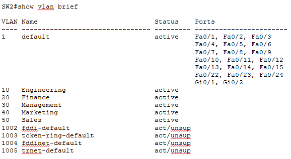
As you can see five new VLANs are present on SW2 though we never did any VLAN configuration on SW2. These VLANs have been learned from the VTP server SW1 through VTP advertisements. You may have noticed in the above output that though SW2 has learnt new VLANs through VTP, no switch ports are yet assigned to these new VLANs. Keep it very clear in your mind that VTP only advertises VLAN information; it cannot advertise VLAN port assignments. Individual switch ports must be manually assigned to desired VLANs on all switches.
VTP Pruning
VLANs are an efficient way to preserve bandwidth by localizing broadcasts, multicasts, and unicast frames. VLAN Trunking Protocols serves the basic purpose of making VLAN management centralized and more efficient. But VTP has a small nifty feature that gives us a way to preserver bandwidth even further within a VLAN. This feature is called pruning. VTP pruning enabled switches send broadcasts to only those trunk links that actually must have the information. Let’s explain it a bit: If SW1 does not have any ports assigned to VLAN 2 and there is a broadcast generated in VLAN 2, that broadcast would not traverse the trunk link from a connected switch to SW1. In other words, other switches connected to SW1 would not send any broadcasts generated in a specific VLAN to SW1 if SW1 has no port assigned to that VLAN, if VTP pruning is enabled.
When we enable pruning on a VTP server, you effectively enable it for the entire VTP domain. By default, only VLANs 2 through 1001 are pruning eligible, but VLAN 1 cannot be pruned because it is the default administrative VLAN. VTP pruning is disabled by default but it is a good idea to enable it to save some bandwidth. And you know what, the configuration is surprisingly simple:
Enter configuration commands, one per line. End with CNTL/Z.
SW1(config)#vtp pruning
Pruning switched on
SW1(config)#exit
SW1#
The command show vtp status can yet be used to find VTP pruning state currently configured:
VTP Version : running VTP1 (VTP2 capable)
Configuration Revision : 8
Maximum VLANs supported locally : 1005
Number of existing VLANs : 9
VTP Operating Mode : Server
VTP Domain Name : CertificationKits
VTP Pruning Mode : Enabled
VTP V2 Mode : Disabled
VTP Traps Generation : Disabled
MD5 digest : 0x60 0xDE 0xD6 0xAC 0x3F 0x23 0xF6
0xC6
Configuration last modified by 10.0.1.1 at 3-1-93 02:07:25
Local updater ID is 0.0.0.0 (no valid interface found)
We can do similar verification on SW2:
VTP Version : running VTP1 (VTP2 capable)
Configuration Revision : 8
Maximum VLANs supported locally : 1005
Number of existing VLANs : 10
VTP Operating Mode : Client
VTP Domain Name : CertificationKits
VTP Pruning Mode : Enabled
VTP V2 Mode : Disabled
VTP Traps Generation : Disabled
MD5 digest : 0xFE 0x30 0x2D 0xC4 0xDE 0x08 0xBA 0x01
Configuration last modified by 10.10.30.1 at 3-1-93 05:00:00
SW2#
Now, if we issue the show interface trunk command on SW2, we discover some interesting facts supporting our understanding of VTP pruning.
SW2#show interface trunk
Port Mode Encapsulation Status Native vlan
Fa0/13 on isl trunking 1
Port Vlans allowed on trunk
Fa0/13 1-4094
Port Vlans allowed and active in management domain
Fa0/13 1,10,20,30,40,50
Port Vlans in spanning tree forwarding state and not pruned
Fa0/13 1
Because there are no switch ports assigned to any of the VLANs 10, 20, 30, 40 and 50 on SW2, all these VLANs have been pruned as shown in grayed output above. VLAN1 cannot be pruned being the administrative VLAN and the same is reflected in the output.